
So there you have it, you’ve designed your first electronic circuit and your now ready to make a million dollars from your glorious creation..
But wait..
Maybe the presentation is a teeny bit bit lacking! Hasn’t really got that Apple refinement and polish.. No problem you say, this can be easily solved in the time old tradition of many a electronics hobbyist..

Hmmm, I wonder if there is another way?
–
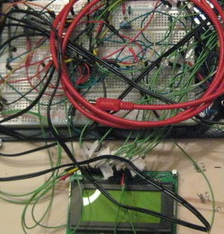
I had the same problem recently with a very small project for a local company, the project was the simplest you could really get, a seven segment 2 digit display and a simple counter circuit triggered by a current transformer detecting a current in a wire, breadboarded in an hour and the 60 lines of code knocked out in the same but what to do for presentation, this unit was going to be bolted to a commercial piece of equipment and even worse was going to be customer facing! No more than 6 will be built so I’m not going to go to any effort to manufacture a case, so what about commercial cases I hear you ask.. well yes you can make a good effort if you’re good with drills and routers, but what about another way, something that achieves a professional finish at less than the cost of a commercial enclosure?
What about something like this.
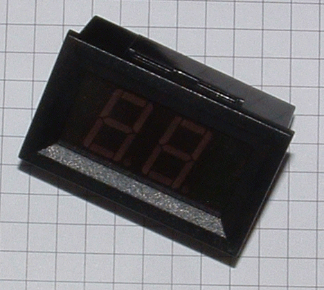
The secret is one I’ve used a few times in the past to create a professional looking project which is to buy something similar with the perfect case and spin your PCB to the exact same dimensions so it fits like a glove.
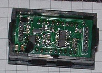
The donor enclosure in this case was from an ebay voltage panel meter several of which are on ebay costing from US$4 each like the example below the first picture is the original PCB and the second picture is what it looked like before removal.


So for four bucks and a ruler we can now get the exact PCB size, then we spin the board into the new footprint and hope that when it comes back from the fabricators everything fits. Luckily in this case it did. (even with me having to use a TO92 regulator as my sot-23 one had’nt arrived yet!)
So what does it do? Well this is basically a timer triggered by sensing a voltage on a solenoid (using a non-invasive Current Transformer), the circuit and PCB are at EasyEDA here
The board fits inside a professional coffee machine and the CT is connected to the grinder servo wire. Once the servo activates the current is sensed, amplified and rectified into a logic level detectable by the PIC which starts counting up in seconds, at 35 seconds it starts flashing to indicate to the barista that the perfect time has been achieved and they can turn it off.
The PIC16F505 is a funny beast, its basically the bottom of the PIC range costing $0.55 in single quantity, it has bugger all RAM, no interrupts, no ADC, not a lot of anything really, its actually ideal though in retrospect I would spend $0.10 more and get something a bit less primitive. The code is here