
Warning: I am still at the prototype stage, this means the system is by no means ready and target date for hardware is end of end of 2013 and for the software the early 2014 depending upon other commitments. It may be best to bookmark the page and come back to it when its all working if you are not keen on reading up on the disasters that I will ultimately make 🙂
The Prototype
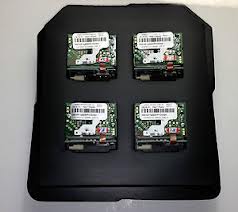
The first prototype board will be custom made for the Hammond 1553 series case so it looks fairly good when I show the prototypes to potential customers in 2014, this is a small handheld case about the size of an iphone 4 but 3 times deeper, into this I have to fit the TFT screen, barcode reader, wireless comms battery and PCB. Quite a squeeze so it may get a bit cramped. As there will probably be plenty of disasters and prototypes I will stick them on separate blog pages.
The Rev C schematic is here
MCU
I’m using the PIC32MX450 which is about $5, has 256KB Flash with 64K Ram which should be adequate for the project. There is no reason why different CPUs families such as ARMs or AVR chips cannot be used if you prefer, but you may need to tweek any low level code for your particular device.
I’m coding using and the free MPLAB-X IDE compiler but I will try and keep the library very simple, with just a single #include so you can modify it easily. While I love the Arduino concept and use it for quick prototypes you really need a proper IDE with integrated debugging, code completion etc to make your life easier when you get past a few hundred lines of code, however this chip is similar to the ones used in the Arduino compatible ChipKit MPIDE or Pinguino IDE so it should not be too difficult to download the appropriate boot-loader off their respective sites.
Touch-Screen
This was purely chosen due to its form factor and price. The East-Rising ERTFT028-4 can be bought directly from buy-display.com for US$9 (including touchscreen and the 50 way ZIF connector) It uses a standard ILI9341 graphics controller which is pretty well documented. Controllers and TFT screen manufacturers come and go but the interface seems to be pretty consistent and we are using a standard 8080 8-Bit interface which should be easy to convert to other TFT displays and controllers should you need a bigger screen or this one become obsolete. Future prototypes may try and use a transflective screen which is a bit more pricey but they are sunlight readable and should need less back-lighting.
WI-FI
The first prototypes are using a Roving Networks (recently bought by Microchip) RN-131 WiFly Serial module. The reasons were purely because I had already used one and was familiar with it and again had some left over. This is probably a quite easy and obvious area to change to lower the BOM cost as there are a few similar and lower cost devices out there which seem to perform the same function and can be had for sub $20. As we are simply using a UART to communicate to it most of the configuration is in the form of sending text commands and waiting for responses, this would be a quite easy change. The RN-131 however has excellent low power consumption, a high power mode for more reliable and longer distance communications and fast start up mode which fits in well with a mobile device and prolonging battery life.
Again, if the price of the RN-131 remains at the US$36 mark it is likely for future versions I will probably evaluate some of the sub-$20 units
Bar-code Scanner engine
Now we get to the most tricky component. (What the MCU wasn’t!)
There are no open source bar-code engines and documentation is either very proprietary or shoddy and costs are generally over US$80 high unless your buying in multiples of 100’s. My first thoughts when designing the prototype were to have a TTL CMOS camera chip and do the image processing necessary to “photograph” a bar-code and convert it to EAN, CODE13 or whatever. This was tricky but do-able, however this was before I actually talked to the guys who need to use these devices and found laser scanners had a much superior performance in warehouses due to the range. Should the scanner only be for job sheets and stock code at close range then there are some small 3.3V matson units I also evaluated for sub-US$40 for 20 off qty.
I was really luckily in this case and found some low cost (and now obsolete) Symbol SE-1223 modules on e-bay and bought 40 for US$13 each. The module is actually very well documented and basically does all the work including decoding the various symbologies and uses a simplified serial interface to the MCU, the only real issue is it is a 5V device and needs a few extra components to boost the lithium battery power to 5V and to convert the levels up from the 3.3V that the MCU uses (groan!)
As this is probably going to be the most common component swapped out it is important to isolate the hardware completely; The library will therefore simply have a ReadBarcode() function to hide any complexities of this, this read function will take care of waking the scanner up from sleep, scanning a bar-code and putting it back to sleep mode. Bar-code scanners can use a lot of juice so the power management side of this is crucial. The connection for the SE-1223, like most others, is via a 12 pin FFC (Flat Flex Cable and Connector)
I wrote a blog post on this and the other options
RFID Reader
The Melexis 90901 chip is a single chip 125Khz RFID reader which just requires a few resistors, capacitors and a 125Khz tuned coil/capacitor to provide a simple RFID reader. Output is a Manchester encoded 2/4Kbit data stream and there is a low power mode. My requirement was for EM4100/125Khz as this was the system currently in use at my major customers and RFID tags for this are only a few cents each on eBay.
13Mhz systems seem to be as common these days and similar solutions exist for these, the advantage being the coil can probably be integrated on the PCB where as the 125Khz cannot.
Again we will be isolating the hardware by using the library ReadRFID() function to wake it up, do a scan and put it back to sleep so you only turn it on to read a tag, the hardware is therefore irrelevant, so long as it is well documented and the library changed to work with the new hardware.
Battery and power
The device will use a standard usb mini connector and I’ve already gone through a couple of changes here replacing my Microchip standard parts with lower cost ones.
We need a LIPO charger chip so we can re-charge the battery from USB, the TP4057 is probably the commonest one out there and worked fine in a small prototype, I managed to order 50 of them for $10 without any serious shopping around.
I really am no expert on batteries and I’m on quite a big learning curve, I’ve obtained a couple of 3.7V 1000mAH cells which I’m hoping will suffice for the power source. I’m sure a serious amount of work will need to go into the software to ensure we have a long battery life, should be fun!
We also need a couple of 3.3V regulators to power the various devices. I’ve used two in this circuit, one for the CPU and WiFi and TFT Logic and the other one for the backlight as it is PWM modulated and I wanted a bit of isolation from the noise it would generate. Again the XC6206MR is about the most common and cheapest (about $0.20 each), it is my first time to use it but I’m not anticipating problems.
The last part of the power circuit is the 5V buck regulator and again I’ve swapped out my standard Microchip parts for a more generic and lower cost chip, again to hopefully save money without loosing any benefit of quality. I have not used the NCP1410 before and I am using the reference design straight off the manual in the design (So what could possibly go wrong!) Just remember the buck regulator needs to be able to satisfy the large surge current for the barcode reader.
Enclosure and mechanics
Strangely this is probably the most complex area for an electronics engineer such as myself to do, putting together the above components and not making it look like a bad school science fair project is really hard to achieve. There is really nothing more disheartening than making what you consider a great piece of electronics and not finishing the package with a great looking case.

- Prototype Case
I would really like to achieve a professional looking system to show to my customer, I want the first impressions to wow them as much as the electronics inside, not for them to sit there thinking my son could have done better than this..
I will be trialling a Hammond 1553 series commercial case and using a CNC router and custom fit PCB to see if a good result is achievable, if not I will be taking it all to Hong Kong in January to see about getting a custom case design made.