The TSL1401 chip is a 128 bit x 1 analogue image sensor in a prototype friendly 8-Pin DIP package. The DIP Package was one of the main selling points for this project but unfortunately looks like its being made obsolete by a surface mount equivalent, however as it is still available and I have plenty of the DIP versions in my parts bin I will not be making a surface mount version of the sensor for the foreseeable future.
The first prototype used the Parallax Linescan Sensor Daughter Board which made checking it was fit for purpose real easy, the site contains a mountain of easily digestible information on using the device including a really well written manual even describing a similar bottling line sensor. Much of the information used to build the first prototype came from here. The Parallax forum also has a few good threads describing the device, this in conjunction with the datasheet is all you need. I will sort of assume you will read these if you want to follow the rest of the text. (Note the links are off-site to save my small monthly bandwidth allocation, but please report if broken or email me if unavailable and I will link to copies here)
Another reason the TSL1401 was considered was because at the time I found the documentation for the CMOS VGA Sensors (such as the OV7720) a bit daunting and had a very short time-scale to get a working system going, I assumed the speed of the bottling line would also be too fast for it. Looking back on the choices, as you always do, a VGA sensor can be programmed for much lower resolutions and could have easily done the same task as we can take a complete image not just a line, however the TSL1401 is much easier to understand and simpler to work with and program.
The PIC32 was originally chosen for a similar reason. I wanted a DIP MCU that could handle 50,000+ analogue to digital conversions a second I would need to clock out of the sensor that is 128 bits clocked out twice (once to clear sensor and second time to clock out actual data) and running at 200+ samples a second (rate determined by the max speed of the bottling line which is 500mm/second and minimum number of samples I need across the bottle width, I determined I needed ) the MCU had to do the above and do the processing of the data to determine a pass fail, the smallest least powerful version is all that is required, these are under $3 in single quantities and is available everywhere ( I use the Microchip Direct site, which can ship the devices to me in New Zealand in under 5 days, though the cost of the courier and amount of packing they use for such small products does leave a lot to be desired!)
The principle of operation is that we have a strong back-light, lighting the bottle from behind. This needs to be white (due to different bottle colours) and have a very even light diffusion across its surface and has to be bright enough to both overcome any ambient lighting (such as florescent tubes which also flicker at 50/60Hz and cause interference . The first versions tried narrow back lights (LED aquarium lights to be exact) but the curvature of the bottle seemed to cause spurious reflections and the alignment of the sensor to the back light meant we needed to be very mechanically precise, millimetre changes seemed to cause the light level to fluctuate enough to throw off readings. The prototypes and the eventual production versions therefore now use 7″ TFT LED back lights which are perfect for the task once enclosed in an appropriate industrial housing (as below) the parts are readily available and cheap but tricky to find, I got mine for US$4 each from wayengineer.com (or you can of course dismantle an old TFT screen)

Note that you should not use older type CCFL back lights as these do tend to flicker and can cause false readings, unless you are prepared to compensate for this, stick with LEDs or incandescent bulbs. As setting up and testing the sensor was going to be a major problem and most of the testing would need to be done live (waving a bottle in front of the sensor just doesn’t cut it and gets tiring very quick!), like the parallax equivalent I needed some sort of PC control program with which I could view real time data, set the focus and back light, record data off-line (so I could debug at home instead of next to a bottling machine) and change values that may be required. The program I wrote to do this is written in Lazarus which is a free and better (IMHO) version of Borland Delphi, the source is Pascal and real easy to read/write even if your a C Programmer the code can be edited and compiled under Windows, Linux or Mac. The Windows exe is included in the files below if you don’t want to install Lazarus and compile from source.

The program (above) connects to the sensor using a Bluetooth UART. The sensor processes serial data only during non-critical times (ie not when aquiring images or during timing/image processing loops) The main advantage of being able to record the sensor data as I mentioned is the ability to try different image processing algorithms off-line. As you can see above I have recorded and am playing back a signal picked up from a white wine bottling run, below is one from a red wine run (Note how the bottom lobe of the white wine is absent from the red wine as it is absorbed by the darker wine)

These signals vary a lot due to bottle opaqueness, speed of line, amount of shaking, frothing of the liquid at the top of the wine, back-light strength, focusing, exposure etc, and just for fun no two signals are ever the same!
To deal with a lot of this, we take a minimum of 12 samples of the bottle neck as it passes the sensor and then average them. The averaging takes away the problem of line speed and reduces the effect of the odd bad image on the final signal, the signals you see above are an average of 25 and 41 samples respectively (the bottling line was moving much faster for the white wine at the time)
The sensor is manually positioned by the operator to be at the centre of the fill line (it is mounted on a screw-line and can be adjusted up or down to accommodate different size bottles). We are therefore expecting a perfectly filled bottle to generate a dark band at the exact centre pixel position or pixel 63. In the above shots the green line is set at 63 to show the expected level and the white line shows what level the algorithm detected (it got the white wine spot on but failed to get the correct level for the red wine). If the detected level falls below the tolerance (marked by the upper and lower red lines) it is considered a fail.


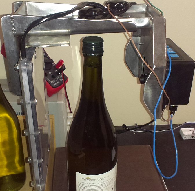
The TSL1401 is mounted on the rear of the PCB in a socket. Directly under it is the cut-out for the lens. If you have done your cut-out correctly the lens will focus the centre of the image onto the centre of the sensor array. the large back-light helps keep this precision down.

The case is a standard Hammond 1591CSBK ABS enclosure with the flange lid. The PCB is mounted on the lid (screw holes in PCB are designed for this) and the lens housing is mounted below. The version C PCB also was going to use a laser line to position the sensor to the bottle fill line but this was a bit of a bad idea as it added no real value, increased cost and you then had lasers shooting around to worry about, a marker pen at the point where pixel 64 lies is all that is required.
Depending upon both the lens used and the distance of the bottle from the sensor and the sensor from the back-light we may not get out signal to completely fill the 128 pixels, neither do we care about the regions outside our area of interest! Therefore during set-up we test the image and cut-off the top and bottom of the signal outside our area of interest using two parameters, neck and cap which removes any data outside of this area of interest.
From many hours of sorting through the live data I have determined the best detection method is to look for the largest falling edge of the signal excluding the edges which rise and fall quite quick after the image is enhanced.
If you consider the captured and processed data to be in an 128 byte array ( unsigned char data[128] ) we detect the falling edge in two passes, the first pass to detect the size of the biggest fall (scanning the arrays area of interest between cap and neck fully) , and the second pass seeking the position it occurred in the array. (see code)
Note in practice we can run several detection algorithms one after the other, catching the low hanging fruit first. The one described above is the best in most cases and is the only one I run, but in some cases we may need to look for weaker indicators of the fill-level (ie by lowering the Value of MinAcceptableFall), Rather than doing that, in the production code I also run some different fill detection processes to accommodate different types.
However it is important you remember the fill level may NOT be found. Such as when the level is below or above our area of interest. There will always be one or two bottles which the level may be obscured by some sort of noise (water or foam running down the bottle, vibration, etc) and you should not tweak your code so much to accommodate these rare instances in case it accidentally starts finding good fill markers in badly filled bottles! 99.8% accuracy is an excellent target to achieve, ie 1 false positive in every 500 bottles, if you are only processing a single type of wine/bottle this should be achievable, however if your bottling line supports several different bottles or wines then expect this value to reduce especially for very clear or opaque bottles or very dark wines, where you may need to write further algorithms to reduce/increase exposure times or do a better detection job.
The only comeback of false positives is that they have to be manually inspected by a human, the comeback if you don’t detect a bad fill is the companies reputation for quality!
The current algorithm is about 99.5% accurate for white wines in normal light green bottles and 99% for reds and darker bottles, I suspect really transparent bottles will not work unless I lower the exposure time considerably I’m working on the algorithm for the Revision D board now. The working files for the revision C PCB have been removed and the final versions are on the next page, the explanation for all versions of the hardware are pretty much the same though
Next >> Finished Design